More Final Images
Tesselion is located at the Philadelphia University Architecture & Design Building & will be up until October.
Address : 4201 Henry Ave. Philadelphia, PA 19144
Feel free to visit & take photos (send me any images & I will post them on the web)!


Tesselion Complete!


Images from the completed installation,
Tesselion: Adaptive Quadrilateral Flat Panelization.
Material Sponsor: Alliance Metals ( www.alliancemetals.com)
Fabrication Sponsor: Jared Laucks & Continental Signs ( www.continentalsigns.net)
Many Thanks: Jared Laucks, Marc Fornes, Adrienne Yancone & everyone else for the generous support!
More images soon!
Construction Day 17_5:4:08
A few photos as the canopy touches down with the ramp.

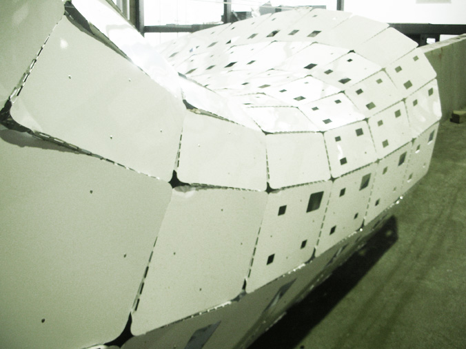


Assembly has been completed: (Final photos will be up soon!)
-All panels are in place & tightened with lock nuts (except 1 which needs to be cut & shipped to site).
-The entire construction including folding, rivetting, bolting, installing & tightening took roughly 7 (12 hour) days for with only 1 person.


Construction Images Day 8_4:25:08


Images from Phase 2: (12) 4’x8′ sheets CNC fabricated by Continental Signs and Jared Laucks. (www.continentalsigns.net)
2 Full strips (27 panels) have been folded, riveted and bolted together. 5 strips still to be assembled. There are 187 total panels in the canopy structure.


Construction Images_Day 6_4:23:08


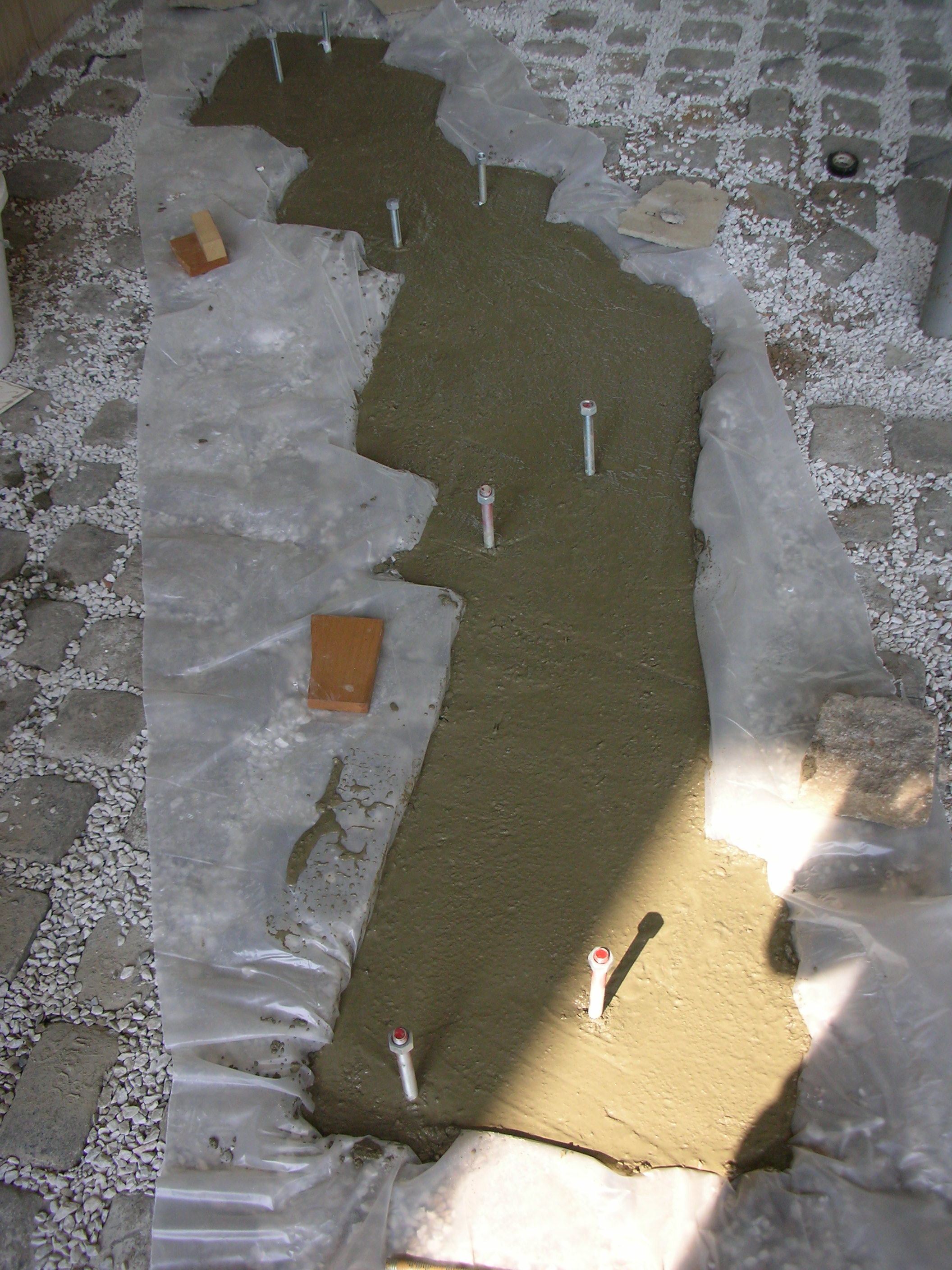
Images from the ground work construction. 2″ Concrete base to stabilize ( 8 ) 5/8″ x 2′ threaded rods driven into grade. Leveling nuts and gaskets will secure the base panels to the threaded rod.


Construction Images_Day 1_4:17:08
A few images from the final assembly. 5 sheets have been CNC routed and delivered, 20 still out for fabrication.
Many thanks to the material sponsor, Alliance Metals (www.alliancemetals.com), for providing ( 28 ) 4′ x 8′ sheets of 1/16″ white aluminum!


Mock-up 4_3:29:08
Images from a fourth full scale mock-up from 1/16″ aluminum sheet. (1) 4’x8′ sheet including 9 full panels and folded connections.
Many thanks to Jared Laucks and Continental Signs for fabrication.


Small Scale Model_3:26:08
A few images from a small scale paper strip model looking at overall weight distribution & surface balance.


Connection Update_Mock-up 3
A few images from a third full scale mock-up, looking at 1/16″ aluminum’s folding capability.
Many thanks to Jared Laucks & Continental Signs for fabrication and photos!


Full Scale Mock-up v.2
A few images from the second full scale mock-up…


Conclusions:
-1/8″ Aluminum may be excessive in weight for panel + tab connection
-A perforated score @ 1/8″ aluminum is very difficult to bend. Either the panel must be 1/16″ thickness or use a channel notch, which may only allow for 90 degree folds.
-Folded connection is very clumsy looking, may go for a triangular shape as well as cut away most of the back face of the connection b/c the first fold restrict almost all of the force
Tab Connection_2
A new tab connection which folds back on itself to restrict unfolding. A full scale mock-up has been sent for fabrication.


FEA Analysis_Prelimary Attempt 1
A few images showing very preliminary FEA analysis.

Axial stress with an aluminum pipe cross section.

Shear stress with an aluminum pipe cross section.

Axial stress with an aluminum “T” cross section.

Shear stress with an aluminum “T” cross section.
Analysis includes:
-Evenly distributed loading (Inaccurate!)
-Axial & shear loading calculation for 2 cross sections
-“T” cross section appears to resist more loading and force high stress areas to the lower right landing of the surface.
-Provides generic feedback for the surface generation….
1/8 Scale Assembly
More images from the 1/8 scale model….


Conclusions:
-The tab connection does not restrict unfolding and requires further bolting to ensure stability.
-A tab connection can reduce overall elements from 1000+/- to 250+/- as connections are incorporated in the panel. This probably doesn’t save money in material cost but drastically reduces assembly time and frustration!!
-Tabs were scaled based on panel edge lengths and therefore varied the size & hole distances.
-The fenestration seems to weaken the panel if it occupies a large percentage and nears the edges.
-Material width was not accounted for and would result in a 9″ increase in the overall full scale length!! This means that all panels must be reduced by 1/8″ to account for the 1/8″ tab fold, or the fold must be set inward.


1/8″ = 1′ – 0″ Scale Model Preparation_2:26:08


The code has been updated to:
-nest all text & panels
-Control the orientation of the connection, either inside or outside
The 1/8″ scale model will use a “tab” connection as the scale is too small to demonstrate the accurate connection. The tab connection also utilizes the possibility of folding each panel with 1/8″ scale materials. Two holes are provided in the tab connection to account for a standard staple to replace the full scale bolts. The tab restricts almost all axis of rotation and should provide an estimate in the overall structural efficiency of the form.

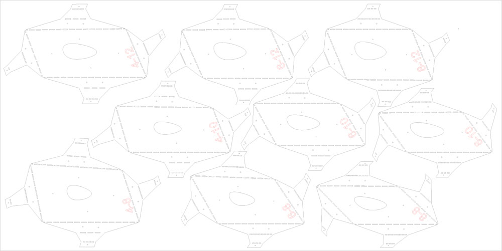
1 of 4 nested sheets including:
-Tab connections
-Fenestration
-Unique 2 digit number

Connection Nest_2:25:08


The code has been updated to:
-add flat panels
-add connections on all interior panels, all edge panels still to be updated
-add three-digit annotation
-flatten and array for nesting on sheets
Still to be updated:
-edge connections
-flatten and array text
-add connection holes & tab
-possibly align perpendicular to panel
Three versions of the connection through code….

The most recent connection which eliminates the “U” shape and minimizes the arm lengths. Still 2 up & 2 down with annotation.

A “Z” shaped connection which may be likely to unfold….

An early “T” shaped connection….

A first nesting attempt…
Connection Annotation_2:25:08
A few images of the connection annotation. A three-digit number is applied to each connection describing:
-The number of the panel in the x direction
-The number of the panel in the y direction
-The edge of the panel : 0,1,2,3


This image shows a version with 2 connections up & 2 connections down for each panel.
A second iteration was produced which gradients the normal of the connection based on the surface curvature. Not sure about its structural consequences but could be a nice detail….
Connection Tolerance per Iteration_ 2:25:08

Connection tolerance with a 10×35 panel layout. Red dots indicating the panels connecting with a .001 tolerance.

Connection tolerance with a 10×30 panel layout.
The tolerance between panels does not directly influence any structural or connection factor as the connections account for each condition individually. However, this did influence the processing of coding and resulted in an interesting discovery relating to the angle and intersection of panels with relation to the various degrees of surface approximation.
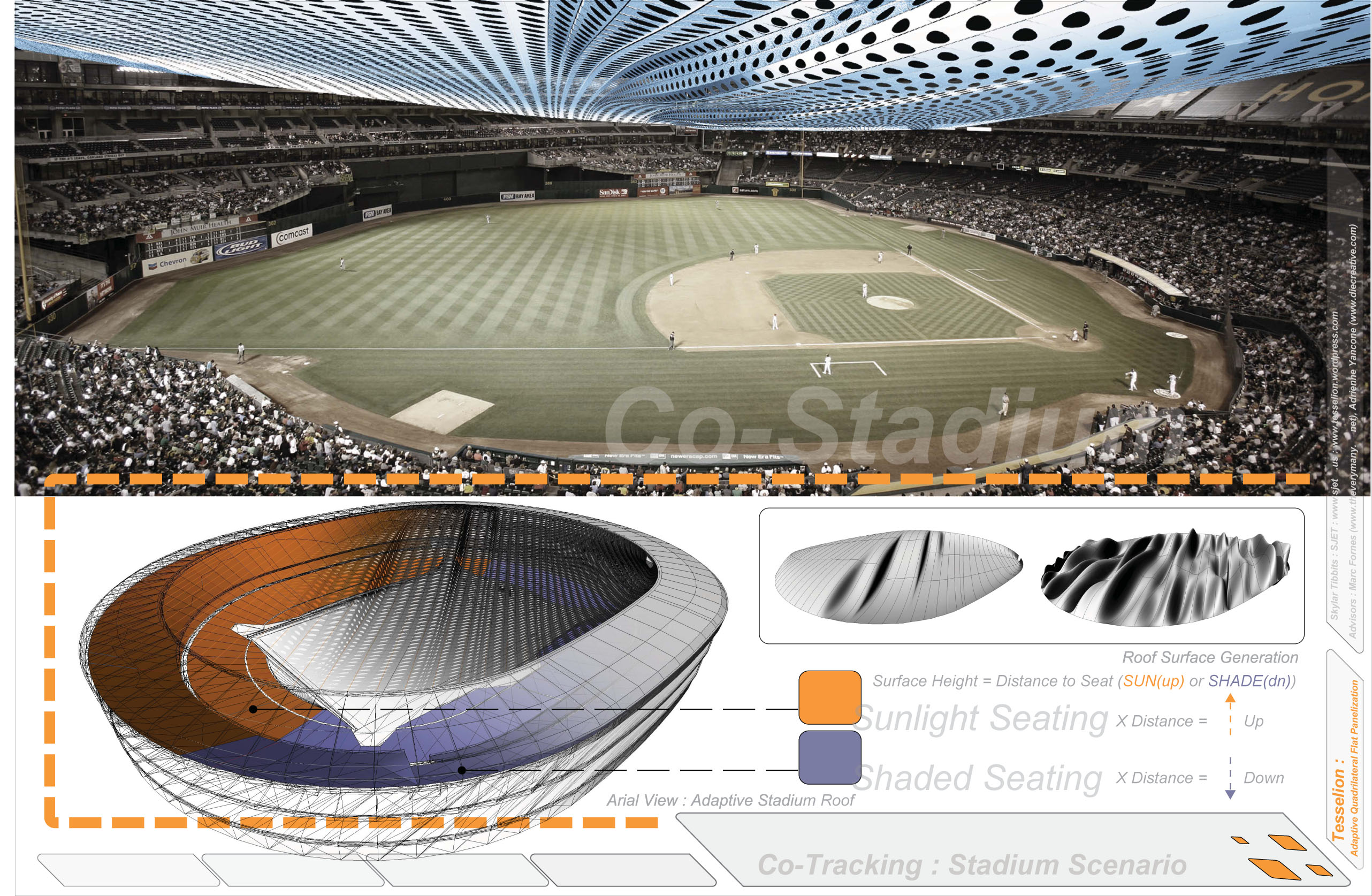
Surface Generation 2:22:08
Two images of the progress of surface generation. The surface now provides occupation and user interaction on a variety of levels while responding to site conditions. The fenestration and connections still need to be resolved.
Demonstrates a 20×50 panel iteration.
Surface Generation_Fitness Criteria 02:22:08
A number of panel variations leading to fitness criteria based on budget, aesthetic surface approximation, structure, and overall weight.
Each iteration demonstrates a decreasing number of panels to approximate the original surface from 30×70 panels to 10×40.
Each iteration is further analyzed based on total material used and the resultant budget for material and connections.

Connection Update_2:19:08


The following shows six full scale 1/8″ metal connections that were CNC routed and assembled. Many thanks to Jared Laucks for fabrication. Two modules were tested: 1. a tooth & notch connection, 2. a bolted tab connection.
Results:
-The tooth restricts the connection from sliding into the panel notch. This results in weakening the metal connection as it requires a bit of forcing!
-The tooth must be longer than the current 1/8″ to ensure that it does not slip out of the panel. Though, this would make the connection even more difficult to slide into the panel notch??
-The tab for the bolt connection on the panel cannot be folded by hand because there is minimal leverage. This requires more surface area in the metal piece OR a thinner gauge metal!! Both will be tested for structural integrity.
-Material thickness needs to be taken into account i.e. a slot must be cut in the panel to offset the material inside the panel and allow each panel to meet perfectly. The metal tab for bolting also did not take material thickness into account.
-A “v” notch should be used, rather than a channel, to score the fold lines. This would ensure that all angles meet @ 90 and minimize error.
-If a tooth & notch connection is used, a larger bottom piece should be added to ensure strength.
-Add 1/8″ to all notch cuts in the panel and metal connection as a router cannot cut square notches…this resulted in 1/8″ on both sides being unusable.
All slight failures aside, the connection worked very well and added up to the exact angle for each panel in both axis!!!!
More to come!


Quad Mesh
Tesselion uses a method of planar quadrilateral meshes to tessellate complex surfaces. The following is a diagram showing the stages of panelization.

The following image demonstrates the range of possibilities using the Tesselion method of panelization. The middle range shows the target surface generation for construction in mid May. The surface criteria fall between limitations in timeline, budget, and small scale structural concerns, otherwise practically any surface can be constructed using the Tesselion method.

Fenestration Studies
Fenestration Studies showing aperture dilation and gradient patterns of optimal environmental conditions.


Connection Tests_2:12:08


A number of connection options to solve the following criteria:
-Resist two axis of rotation
-Resist panels from pulling away from each other
-Maintain structural integrity as it may carry most of the load
-Fabrication with either 3 axis CNC router or laser cutter, requiring flat sheet material
